Friday, March 12, 2010

Exporting a 3D Model for people that don't have Revit


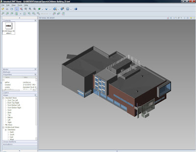
You can export a 3D DWF directly from Revit. The file can be opened with DWG TrueView which is free to download from Autodesk and is preinstalled on many new computers.

The advantages of the 3D DWF are that people can rotate and look around the entire model. It looks similar to the Shading with Edges Inside of Revit. The files sizes are much smaller than the Revit file which makes them easier to send out. You can also sun sections in the dwf to look inside the model.

1. Export > DWF
2. Select a 3D view in the model
3. Hit Export

This could be helpful to show clients, contractors, or consultants. It could even be useful to just have one that gets updated periodically in a standard location so that project managers/partners can open it whenever they want to take a look at the model.

Wednesday, March 3, 2010

Can't Edit until someone Relinquises and that person is gone

If someone is gone but still owns elements that other teams members need, there is a work-around.


1. Get that person's username (look in the Worksets dialog box)


2. Get everyone in the Revit project to Save/Synch to Central and exit the file


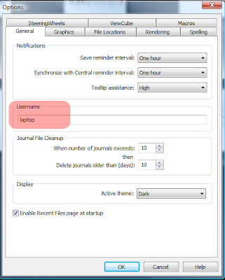
3. With the project unopened, go into the Options menu and change your username to the username of the other person


4. Open the Central File

5. Collaborate>Relinquish All Mine

6. Check Worksets to make sure that user no longer has ownership of any worksets

7. Save and Close the Central File

8. With the project unopened, go into Options again and put your username back in

9. Everyone should now be able to reopen their files and continue working


Tuesday, February 2, 2010

Keyboard Shortcuts

Some of the Keyboard Shortcuts in 2010 that would be useful are missing or just are not he same as the ones that were in 2009.

You can add/edit to the KeyboardShortcuts.txt file that should be located here on your computer:

C:\Program Files\Autodesk Revit Architecture 2010\Program

Most of the commands are already in there (though it may take some scrolling to find them), but they have a blank value. Just put in the initials you want for the shortcut in quotations following the same format as the other entries.

So I changed these two lines

; "" ribbon:"Detail-Detail-Masking Region"
; "" ribbon:"Detail-Detail-Filled Region"

to this to get Filled Regions and Masking Regions to work.

"MR" ribbon:"Detail-Detail-Masking Region"
"FR" ribbon:"Detail-Detail-Filled Region"

After saving your modifications you have to restart Revit. The shortcut initials that you put in will also show in in the roll-over help menu when your mouse is above a command in the ribbon.

Monday, February 1, 2010

Lines of Trees

How many times has a partner (e.g. Tim) wanted you to show a row of trees in a Revit elevation and have the trees line up with mullions 150ft away on the other side of the building?
If you need to quickly create rows of trees, use a custom curtain wall family. A curtain wall family is more versatile than a line based repeating component because it allows you to:
  1. leave out certain trees (by setting the cutain panel to blank)
  2. use different types of trees in the same row
  3. space out the trees in different ways (regular or irregular intervals)
  4. use straight lines, curves, and change directions within the same row (with greater control of what happens at the intersections)

The family in the example is called Deciduous Tree Row and is located at K:\2010RAS\Overland\Planting for you to start with.

The RPC Tree - Deciduous family is loaded and locked to the center of the curtain wall panel. It wouldn't stay attached to the end of the panels for some reason.

Tuesday, January 26, 2010

Revit Tutorial Videos


Design Reform – David Fano, one of the AU presenters, has posted a lot of tutorial videos from basics of massing to some pretty complex parametric families.


http://designreform.net/category/tutorials/revit-tutorials/

Thursday, December 10, 2009

Getting objects above to show up in floor plan

Sometimes there are things above the plan cut plane that you want to show up the plan. A ceiling mounted projector and the projector screen are two examples of items that you might want to see on the RCP and the floor plan.

Normally an object hosted on a ceiling will not appear on the plan so you could manually draw in dashed lines for the item. However every time the object moves or changes, you will have to more or edit the lines.

Just adding dashed lines below the object in the Family where the floor would be will not make it appear in the floor plan.

But drawing an invisible line in the Family straight down so that it passes through the View's Cut Plane will trigger it to appear. You can then use the Linework tool to make the lines dashed.

Plan Regions can also be used for this. You will have to create a plan region for each object. So if you have multiple objects of the same Family, the invisible line trick will automatically do make all of them visible.

Tuesday, December 8, 2009

When to use Design Options and Phases

Design Options > small scope changes

When you are creating a design option for an element, anything hosted or affected by that element must also be addressed by each option. So if you are creating 3 design options for a roof, any skylights hosted in that roof have to be addressed in 3 different options. If the change to the roof affects the way a wall connects to the roof, then that wall and anything hosted by that wall has to be part of each option.

So Design Options are effective for small scale changes, but can end up bloating file sizes and creating a lot of work for changes of a larger scope.

Phases > larger scope changes

Phases are not limited to the default "New" and "Existing Construction." They can be used in a similar way to Design Options to show multiple larger scale options. Phase Filters allow you to control the visibility of phases. This is a little more complex to set up than Design Options but can save on the amount of duplicated work.

Multiple Linked Models > large scope changes

If a large portion of the model is changing in each option or you are evaluating different schemes, using multiple linked models may be a better solution. Linking the models allows you to set up side-by-side comparisons easily. Each option is a separate file, so the changes in one will not affect the other. This is only a good option to use when the overall design is still very schematic and large scale changes are happening that need to be evaluated against each other.