2. Start sketching the outer boundary of the trellis with a Roof
Home > Roof > Roof by Footprint
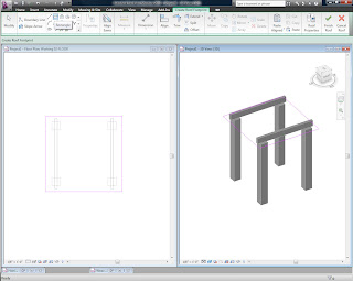
3. Go to the Properties of the Roof and switch the Family to System Family: Sloped Glazing (this is a Curtain Wall used for skylights) and then create a new Type (name it something easy to distinguish from other skylights that might be in the project)
4. Go to the Type Properties
There are lots of setting here that we can tweak to get Revit to automatically generate a simple trellis.
Set Curtain Panel > Empty System Panel:Empty (this gets rid of the glass)
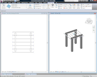
5. Grid 1 and Grid 2 are set to be perpendicular to each other by default. We will use one of them to create the smallest layer of the trellis and the other to create intermediate size beams.
In this case Grid 2 is going to be the intermediate layer.
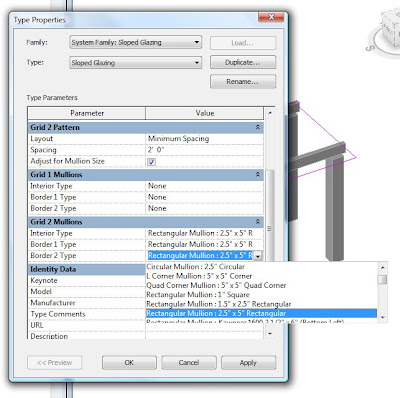
Under Grid 2 Mullion select the profile that you want for the beams (I picked a 2.5"x5" Rectangular shape)
Under Grid 2 Pattern you can adjust the layout and spacing that Revit will use to generate the curtain grid
Now hit Ok to see what you created. If these beams are not running in the direction that you want you can switch this over to Grid 1.
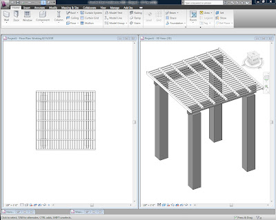
6. Go back into the Type Properties to add the smaller layer to Grid 1 like we did for Grid 2. I chose a smaller profile and closer spacing Grid 1.
I also changed the Join Condition to Border and Grid 2 Continuous. This means that the parts of Grid 2 will not be interrupted by the Grid 1 and give the appearance of continuous beams.
Take another look to see the effects of the setting you changed.
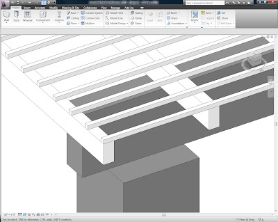
7. This trellis is great for early on in the design process since you can easily change the shape of the roof sketch. But there are a few things wrong with it if you take a closer look. like the fact that the smaller trellis pieces are in the middle of intermediate ones instead of being on top.
8. One thing that is wrong is that the intermediate members stop short. Adjusting the Mullion Joins can fix this.
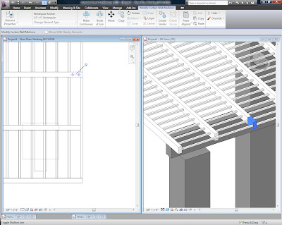
9. The other thing that is wrong is that the smaller trellis pieces are in the middle of intermediate ones instead of being on top. There are a couple ways to fix this. An easy way is to create a copy of the Curtain System above the original. Duplicate the original Type and name it something that makes it easy to tell them apart. Naming them something like Trellis-Upper Layer and Trellis-Lower Layer might be appropriate. In the Trellis-Upper Layer just turn off the grid pattern and mullion profiles for the lower grid. And do the opposite settings in Trellis-Lower Layer.